


When it comes to the quality of the finished item, the choices about design that are taken early on in the project have a far stronger influence than any adjustments that are made later on the shop floor. In order to understand how wall thickness, draft angles, parting lines, and shrinkage allowances impact both the manufacturability and the long-term performance of casting components, engineers and purchasers who deal with these components need to have this knowledge. This article provides a comprehensive overview of the fundamental design criteria that assist teams in avoiding expensive mistakes and producing castings that are dependable and precise in terms of their dimensions.
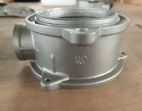
What Design Factors Most Affect Casting Component Quality?
Geometry Simplicity and Uniformity
Creating stress concentrations and making mould filling unexpected are both outcomes that may be attributed to complex geometries that include abrupt transitions or sharp interior corners. Designers who are working on casting components should strive to achieve transitions between parts that are smooth and progressive whenever it is practicable to do so. By simplifying geometry, not only is it possible to optimise the flow of metal during pouring, but it also minimises the chance of porosity, cracking, and partial fill, all of which are typical complaints about poorly designed components.
Material Selection Compatibility
In light of the fact that various metals shrink, flow, and solidify at varying rates, the alloy that is selected has a considerable impact on the manner in which a casting design should be addressed. Prior to finalising the shape, designers need to take into consideration the fluidity, solidification range, and thermal expansion properties of the material that has been chosen specifically. For the purpose of achieving consistent and defect-free outcomes in production, casting components produced from iron, steel, or aluminium each need somewhat different design considerations.
Core and Cavity Interaction
When it is necessary to have hollow parts or interior cavities, core placement and support become very important design issues. During the pouring process, cores that are not adequately supported might move, which can result in variations in wall thickness and dimensional inaccuracies. Before committing to a final design, engineers who are creating casting components should collaborate closely with foundry teams at an early stage of the process to verify core stability, venting pathways, and overall mould architecture.
How Do Wall Thickness and Draft Angles Improve Castability?
Maintaining Uniform Wall Thickness
When it comes to cast parts, one of the most prevalent reasons for shrinkage, porosity, and warping is uneven wall thickness. In the process of the metal solidifying, thicker portions cool more slowly than thin ones, which results in the formation of internal tensions. To reduce the likelihood of hot spots and structural problems, designers who are responsible for the production of casting components should strive to achieve a wall thickness that is uniform across the whole component. This should be accomplished via progressive transitions rather than sudden shifts.
Applying Proper Draft Angles
Draft angles make it possible to extract cores and patterns from the mould in a clean manner without causing any damage to the casting surface or the tooling components themselves. Inadequate draft may result in surface ripping, dimensional deformation, or higher tooling wear over the course of several production cycles. It is beneficial to cast the majority of components with draft angles ranging from one to three degrees; however, the precise figure is contingent upon the height of the part, the material, and the particular moulding technique that is being used.
Rib and Boss Design Considerations
Ribs and bosses are a great way to provide structural strength without considerably increasing the overall wall thickness. However, they need to be properly planned in order to prevent the creation of new vulnerable areas. Sink marks or internal cavities may be caused by ribs that are too thick in comparison to the wall that is next to them. For the purpose of preserving both uniform cooling and structural integrity, casting components that have been thoughtfully developed often retain rib thickness at around sixty percent of the neighbouring wall.
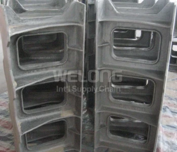
How Does Parting Line Design Affect Casting Components' Accuracy?
Choosing an Optimal Parting Line Location
A direct influence on dimensional accuracy, flash formation, and overall tooling complexity is exerted by the positioning of the parting line, which is responsible for determining the point at which the mould halves split apart. It is possible for parting lines that are not properly positioned to produce visible seams in important regions or to make downstream machining more difficult. Engineers who are creating casting components should choose parting line positions that strike a compromise between the simplicity of mould release and the needs of the completed part when it comes to both its functionality and its appearance.
Minimizing Flash and Mismatch
Flash happens when molten metal escapes along the separating line, which necessitates extra trimming and finishing work after the casting process has been completed. The presence of excessive flash or mould mismatch may potentially be an indication of tooling wear or misalignment problems. Casting components may be kept within tight dimensional tolerances with the aid of careful parting line design and adequate mould maintenance. This helps reduce the amount of secondary labour that is required to clear away extra material.
Impact on Draft and Surface Finish
The location of the parting line also has an effect on the manner in which draft angles are applied throughout the surface of the part. This is because the direction of the draft normally follows the direction in which the mould opens from that line. Undercuts or places that are difficult to complete might be the consequence of poor coordination between the separating line and the draft design. The casting of components guarantees that they keep both correct geometry and appropriate surface quality right out of the mould. This is accomplished via careful preparation.
How Can Shrinkage and Machining Allowances Reduce Casting Defects?
Calculating Accurate Shrinkage Allowances
As molten metal cools and solidifies, it undergoes a certain percentage of contraction, which varies according to the alloy that is being used. If this shrinkage is not taken into consideration during the pattern design process, the finished pieces will be of a smaller size than expected. The use of shrinkage allowances that are particular to each material is something that experienced designers do when designing components for casting. This helps to ensure that the completed dimensions meet design parameters once the part has completely cooled.
Planning Machining Stock Correctly
In order to achieve surfaces that need tight tolerances or fine finishes, it is generally necessary to leave excess material, which is referred to as machining stock, in situ throughout the production process of casting. There is a danger of leaving hard casting skin on the final surface if there is insufficient stock, whereas an excessive amount of stock wastes both material and machining time. In order to facilitate the smooth transition of casting components from the foundry to the final machining processes, it is important to properly balance this allowance.
Addressing Shrinkage-Related Defects Early
Problems on the foundry floor itself are not always the cause of shrinkage porosity, voids, and dimensional drift; rather, these issues are often traced back to inadequate allowance planning. Engineering professionals are able to make accurate predictions about the behaviour of shrinkage across various areas of a part by using simulation software throughout the design process. Casting components may be prevented from requiring expensive rework thanks to this proactive strategy, which also assures more predictable and reproducible manufacturing outputs.
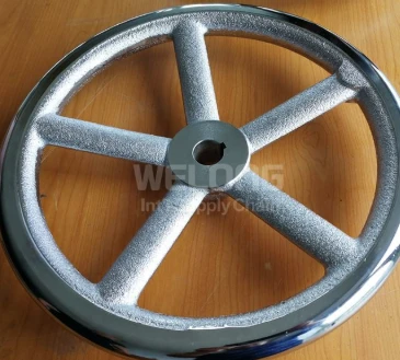
Conclusion
Casting components that are dependable and parts that are plagued by flaws may be distinguished from one another by paying careful attention to characteristics such as wall thickness, draft angles, parting lines, and shrinkage allowances. Customers in the automotive, aerospace, and industrial sectors all over the globe may benefit from China Welong's twenty years of engineering and quality control expertise. China Welong was established in 2001 and is internationally accredited to the ISO 9001:2015 standard. Are you ready to improve the design of your casting? Let us collaborate on the next project you have in mind.
FAQ
What causes porosity in casting components?
Porosity typically results from uneven wall thickness, poor shrinkage allowance planning, or inadequate venting during the mold filling process.
How much draft angle is typically needed for a casting?
Most designs use one to three degrees of draft, though the exact figure depends on part height, material, and molding process.
Why does wall thickness uniformity matter so much?
Uneven thickness causes inconsistent cooling rates, leading to internal stresses, warping, and shrinkage porosity in the finished part.
Can casting design be simulated before production begins?
Yes, simulation software helps predict shrinkage, hot spots, and fill patterns, allowing engineers to refine designs before tooling is built.
How does parting line placement affect finishing costs?
Poor parting line location increases flash and mismatch, requiring more trimming and secondary finishing work after the casting is removed.
Optimize Your Casting Components With Expert Design Support
If you're developing new casting components and want to avoid costly design mistakes, China Welong's engineering team can help. Using AutoCAD, Pro-Engineering, and SolidWorks, we support customers from initial drawing through final production, backed by 20 years of experience serving automotive and industrial manufacturers worldwide. Contact us today at metal@welongpost.com to discuss your project and receive expert design guidance.
References
1. American Foundry Society (AFS), Casting Design Handbook, AFS Technical Publications.
2. ASM International, ASM Handbook, Volume 15: Casting, ASM International Publications.
3. Beeley, P., Foundry Technology, Butterworth-Heinemann.
4. Campbell, J., Complete Casting Handbook: Metal Casting Processes, Techniques and Design, Butterworth-Heinemann.
5. International Organization for Standardization, ISO 9001:2015 Quality Management Systems Requirements.
6. Society of Automotive Engineers (SAE International), Casting Design and Application Guidelines for Automotive Components.


