


The power generation, aerospace, and industrial machinery sectors are continuously evolving, driven by the demand for higher efficiency, greater reliability, and improved equipment performance. At the heart of many turbine systems is the turbine shaft, a critical rotating component responsible for transmitting power and supporting the stable operation of the turbine. But what exactly is a turbine shaft, how does it work, and why is its design and manufacturing quality so important? This article explores the fundamental concept of turbine shafts, explaining their functions, common materials, manufacturing processes, and key applications. Whether used in steam turbines, gas turbines, or other high-performance rotating equipment, understanding turbine shafts can provide valuable insight into how modern turbine systems achieve reliable and efficient power transmission.
Introduction to Turbine Shaft
A turbine shaft is a critical rotating component in turbomachinery that transfers power from a turbine to a load or other machinery. It must withstand immense stresses from torque, rotation speeds, and extreme operating environments. Optimized design, precision manufacturing, and rigorous testing are critical to ensure reliable performance. This article will provide an overview of its functionality, design considerations, manufacturing processes, and quality control.
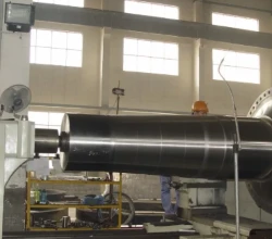
Turbine Shaft Material
Material selection is one of the most important factors affecting the performance and service life of a turbine shaft. Because turbine shafts operate under continuous rotation, high torque, cyclic stress, and, in many applications, elevated temperatures, the selected material must provide an appropriate balance of strength, toughness, fatigue resistance, creep resistance, and thermal stability.
Cr-Mo-V Alloy Steel
Chromium-molybdenum-vanadium (Cr-Mo-V) steels are widely associated with steam turbine rotor applications, particularly in high-pressure (HP) and intermediate-pressure (IP) sections. The combination of chromium, molybdenum, and vanadium contributes to high-temperature strength and creep resistance, making these steels suitable for demanding operating conditions.
For forged turbine shaft and rotor components, controlled forging and heat treatment are essential to achieve the required mechanical properties and microstructural consistency.
Ni-Cr-Mo-V Alloy Steel
Nickel-chromium-molybdenum-vanadium (Ni-Cr-Mo-V) steels provide a combination of high strength and fracture toughness. Certain grades, including 3.5NiCrMoV steels, have been widely used for large low-pressure steam turbine discs and rotors.
These properties are particularly important for large-section turbine components, where toughness, fatigue performance, and resistance to crack propagation must be carefully controlled.
9–12% Chromium Steels
Advanced 9–12% chromium steels have been developed for higher-temperature steam turbine applications. Compared with conventional low-alloy rotor steels, these materials are designed to provide improved creep strength and oxidation resistance at elevated operating temperatures.
Their use is particularly relevant to advanced power generation systems seeking higher steam temperatures and improved thermal efficiency.
Nickel-Based Alloys
For extremely high-temperature turbine applications, nickel-based alloys may be considered where conventional steels cannot provide sufficient high-temperature performance. These materials offer excellent creep and oxidation resistance but are generally more expensive and challenging to manufacture in large component sizes.
Material selection for a turbine shaft should ultimately be based on the turbine type, operating temperature, rotational speed, shaft dimensions, mechanical loading, and applicable technical specifications. In critical applications, chemical composition and mechanical properties should be verified together with heat treatment, ultrasonic testing, and other non-destructive testing procedures to ensure the turbine shaft meets the required service conditions.
How does a shaft work?
In a turbine system, the shaft connects the turbine to the compressor, generator, or other rotating components. It transmits rotational power by torque from the turbine blade to the machinery. The shaft must rotate at very high speeds - up to several thousand RPM in some designs. In addition to torque, the shaft must withstand axial and radial loads from factors like thrust, imbalanced forces, misalignment, and weight. Materials and designs are engineered to provide high strength, fatigue resistance, and temperature capability to handle these demanding operating conditions over long service life cycles.
Key Design Considerations
Critical factors in turbine shaft design include:
Operating environment
The shaft material must be compatible with temperatures, pressures, fluids, and corrosion factors in the system. Exotic alloys are often required.
Rotational speeds
Maximum RPMs determine requisite balance and centrifugal stress capabilities.
Torque transmission
Shaft diameter and material tensile strength must suit torque loads.
Critical frequencies
Resonant frequencies that produce vibrations must be avoided through modal analysis.
Fatigue life
Minimizing cyclic stresses through engineering maximizes allowable cycles before failure.
Reliability factors
Redundancy, fault tolerance, and damage tolerance improve reliability.
By analyzing these factors using advanced techniques like finite element analysis, designs can be optimized for performance, reliability, and durability.

Manufacturing Processes
Precision manufacturing and machining processes are vital for achieving design specifications:
Forging
The shaft raw material is forged from cast ingot or billet into a preliminary shape. Forging aligns grain structures.
Heat treatment
Required to achieve desired material properties like strength and hardness through processes like quenching.
Machining
CNC turning, drilling, and milling machines precisely cut surfaces, diameters, holes, keyways, and fittings to specifications.
Grinding
Grinding removes residual stresses and smoothes surfaces for optimal finish.
Balancing
Precise dynamic balancing eliminates vibration-inducing imbalance.
Surface treatments
Coatings or treatments like carburizing may be applied for added wear resistance, corrosion protection, or lubricity.
Nondestructive testing
Methods like ultrasonic, radiographic, and magnetic particle inspection detect flaws.
Strict process controls and quality management ensure conformance to exacting engineering requirements over all manufacturing steps.

Turbine Shaft Types
There are two primary variants:
Solid Shafts
- Machined from a single piece of material - no joints or welds.
- Maximum integrity for transmitting highest torque loads.
- Used in small turbine assemblies.
- Limitations on maximum diameter and length based on raw material availability.
Hollow Shafts
- Constructed by welding multiple sections together.
- Allow larger diameters and longer shafts than solid designs.
- Bore provides route for cooling fluids or lubricants.
- Additional considerations for weld quality and integrity.
The optimal design depends on size constraints, torque loads, RPM, and other requirements of the turbomachinery.
Quality Control and Reliability Testing
To validate performance and reliability, they undergo stringent testing:
Dimensional inspection
100% inspection of all critical dimensions.
Ultrasonic testing
Detects small internal flaws in the material.
Radiographic testing
X-ray images identify internal defects.
Dye penetrant testing
Reveals small surface defects.
Magnetic particle inspection
Detects surface or near-surface flaws.
Spin testing
Evaluates balance and vibrations at full operating speeds.
Overload testing
Confirms design margins by testing beyond design loads.
Metallurgical testing
Validates material composition and properties.
Reliability testing
Bearing life, rotordynamics, and fatigue analysis.
Comprehensive testing proves integrity, performance, safety margins, and reliability under real-world operating conditions.
Conclusion
It is an elegantly simple but mission-critical component enabling modern turbo machinery. Through rigorous design, precision manufacturing, and comprehensive testing, companies like China Welong ensure turbine shafts meet the extreme demands of power, aerospace, and industrial applications. With proven engineering expertise and quality control, they continue driving innovations enabling cleaner, more efficient energy production and power systems. Please contact us at metal@welongpost.com.
Reference Sources
ScienceDirect: A Nondestructive Method for Estimation of the Fracture Toughness of Cr-Mo-V Steel – Discusses 1Cr-1Mo-0.25V steel, a material widely used for turbine rotors in power plants, and examines its fracture toughness and material properties.
ScienceDirect: Degradation of Mechanical Properties of Cr-Mo-V and Cr-Mo-V-W Steam Turbine Rotors – Studies the long-term performance and fracture toughness of Cr-Mo-V and Cr-Mo-V-W rotor steels after extended operation at elevated temperatures.
ScienceDirect: Research on Low Temperature Brittleness of 30Cr1Mo1V Steam Turbine Rotor Steel – Examines 30Cr1Mo1V steel, which is widely used for high-temperature steam turbine rotors operating at temperatures of approximately 566°C and below.
ScienceDirect: Drum-Type Rotor – an Overview – Provides technical information on steam turbine rotor configurations and discusses the use of 1–2% Cr steels and 12% Cr steels for turbine rotor applications.
U.S. Department of Energy OSTI: Creep-Resistant Ferritic-Martensitic Steels for Power Plant Applications – Reviews the development of creep-resistant ferritic-martensitic steels for high-temperature power generation applications and discusses material performance at elevated operating temperatures.
Frequently Asked Questions (FAQs)
FAQ
Q: What is a turbine shaft?
A: A turbine shaft is a rotating mechanical component that connects the turbine rotor to other equipment in the system. It transmits the mechanical power generated by the turbine and must withstand rotational forces, torque, vibration, and cyclic loads during operation.
Q: What is the purpose of a shaft?
A: The primary purpose of a shaft is to transmit rotational motion and torque between mechanical components. In a turbine system, the shaft transfers mechanical energy from the turbine to equipment such as a generator, compressor, pump, or other driven machinery.
Q: What are the parts of a turbine called?
A: The main parts of a turbine typically include the rotor, shaft, blades or buckets, discs, casing, bearings, seals, and stationary components such as nozzles or vanes. The exact configuration varies depending on whether it is a steam turbine, gas turbine, or another type of turbine.
Q: What materials are used for turbine shafts?
A: Turbine shaft materials are selected according to operating temperature, rotational speed, mechanical load, and turbine design. Common materials include Cr-Mo-V and Ni-Cr-Mo-V alloy steels, while advanced high-chromium steels may be used for demanding high-temperature applications.
Q: What are the different types of turbine shafts?
A: Turbine shafts can be categorized according to their application and system configuration. Common examples include steam turbine shafts, gas turbine shafts, and turbine-generator shafts. Turbine systems may also use single-shaft, twin-shaft, or multi-shaft configurations depending on operational requirements.
Q: How are turbine shafts manufactured?
A: Large turbine shafts are commonly produced through forging, followed by heat treatment, precision machining, and finishing processes. Critical shafts may also undergo ultrasonic testing, mechanical property testing, dimensional inspection, and dynamic balancing to verify material integrity and manufacturing accuracy.
Q: Why are turbine shafts usually forged?
A: Forging can produce a refined and controlled grain structure while reducing the risk of internal defects compared with some alternative manufacturing methods. This makes forged turbine shafts suitable for applications requiring high strength, fatigue resistance, and reliable performance under continuous rotational loads.
Q: What is the difference between a turbine shaft and a turbine rotor?
A: The turbine shaft is primarily responsible for supporting rotating components and transmitting torque, while the turbine rotor generally refers to the complete rotating assembly. Depending on the turbine design, the rotor may include the shaft, discs, blades, and other rotating components.
Q: What causes turbine shaft failure?
A: Turbine shaft failure can result from fatigue, excessive vibration, misalignment, thermal stress, material defects, improper heat treatment, lubrication problems, or operation beyond design conditions. Proper material selection, manufacturing control, inspection, alignment, and preventive maintenance help reduce the risk of premature failure.


