In the world of fluid dynamics and mechanical engineering, the centrifugal pump stands as a cornerstone technology for moving liquids across countless industries. At the core of its efficient operation lies a critical component: the volute casing. This seemingly simple spiral-shaped chamber plays a pivotal role in converting velocity into pressure, making it indispensable for a wide range of applications. This article delves into the design, function, types, and applications of the volute casing.

What is a Volute Casing?
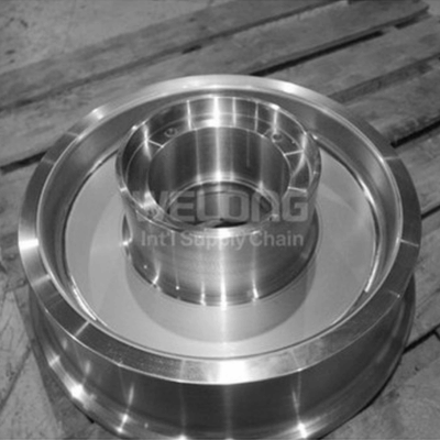
A volute casing is the stationary, spiral-shaped housing that surrounds the impeller of a centrifugal pump. Its primary function is to collect the liquid discharged from the impeller at a high velocity and efficiently convert this kinetic energy (velocity energy) into pressure energy (head). The casing is designed in a way that its cross-sectional area gradually increases from the tongue (the point closest to the impeller) to the discharge nozzle. This expanding area allows the fluid to slow down, and according to Bernoulli's principle, this decrease in velocity results in an increase in pressure.
Key Functions and Design Principles
The design of the volute casing is not arbitrary; it is governed by fundamental hydraulic principles to maximize efficiency and minimize losses.
Energy Conversion: As the impeller rotates, it imparts kinetic energy to the fluid, throwing it outward at high speed. The volute casing captures this fluid and guides it through its progressively widening passage. The gradual expansion is crucial-it prevents turbulence and shock losses that would occur if the fluid were to exit abruptly, ensuring a smooth and efficient energy conversion process.
Hydraulic Balancing (Single vs. Double Volute): In high-pressure pumps, a significant radial thrust force can act upon the impeller due to uneven pressure distribution within a single volute. To counteract this, a double volute (or twin volute) casing is often employed. This design features two separate volute passages, arranged 180 degrees apart, which creates a more balanced pressure distribution around the impeller. This reduces radial loads, leading to less shaft deflection, lower bearing loads, reduced vibration, and extended component life, albeit at a slightly higher manufacturing cost.
Efficiency and Performance: The shape and surface finish of the volute are critical for hydraulic efficiency. A smooth interior surface minimizes friction losses. The design must be precisely matched to the pump's operating conditions (Flow rate and Head) to ensure the pump operates at its Best Efficiency Point (BEP).
Common Materials and Manufacturing
The choice of material for a volute casing depends heavily on the fluid being pumped and the operating environment. Common materials include:
Cast Iron: Economical and suitable for pumping water and other non-corrosive fluids at moderate temperatures and pressures.
Stainless Steel (e.g., 304, 316): Offers excellent corrosion resistance, making it ideal for chemical processing, seawater, and food and beverage applications.
Duplex Stainless Steels: Used in highly corrosive and abrasive environments, such as in oil and gas production.
Bronze: Often used for marine applications due to its resistance to saltwater corrosion.
Specialty Alloys: For extreme conditions involving high temperatures, high pressures, or highly abrasive slurries.
Manufacturing processes typically involve casting to achieve the complex internal geometry, followed by precision machining to ensure proper impeller clearance and smooth flow paths.
Applications Across Industries
Due to their robustness and efficiency, centrifugal pumps with volute casings are ubiquitous. Key sectors include:
Water and Wastewater Treatment: For transporting water, sewage, and chemicals throughout treatment plants.
Oil and Gas: Used in upstream, midstream, and downstream processes for crude oil, refined products, and injection water.
Chemical and Process Industries: Handling everything from aggressive acids and solvents to viscous process fluids.
Power Generation: Circulating cooling water in thermal and nuclear power stations.
HVAC Systems: Circulating chilled and hot water in building heating and cooling systems.
Irrigation and Agriculture: Moving large volumes of water for crop irrigation.
Advantages and Considerations
Advantages:
Simple and robust design, leading to reliability.
Capable of handling a wide range of flow rates.
Generally more cost-effective to manufacture than diffuser-type casings for many applications.
Considerations:
Efficiency can drop significantly if the pump operates far from its BEP.
Single volute designs can generate high radial loads at off-design points.
The casing is a pressure-containing component and must be designed to meet relevant safety standards (e.g., ASME B73.1, API 610).
Conclusion
The volute casing is far more than a simple pump housing. It is a masterfully engineered component that is fundamental to the performance and reliability of centrifugal pumps. Its ability to efficiently transform kinetic energy into useful pressure head makes it a key enabler for fluid transport in modern industry. Understanding its design principles, operational characteristics, and proper application is essential for engineers and technicians tasked with selecting, operating, and maintaining these critical assets. As pump technology evolves with computational fluid dynamics (CFD) and advanced materials, the volute casing continues to be refined, pushing the boundaries of efficiency and durability.
Contact Us
For more information, please contact us at metal@welongpost.com.